

 Product
 Brand
Brand Articles
 Tools
Tools
Commonly Used Circuit Protection Components: How to Match the Right Device to Each Threat
Introduction to Circuit Protection
Every board that connects to a power input, a cable, or a human hand faces electrical stress the design did not plan for. Circuit protection components absorb, divert, or cut off that energy before it reaches the parts you care about. Because no single device handles every threat, good design starts by naming the threat and then reaching for the family built to answer it.
Catalog
Overcurrent Protection: Fuses, Resettable PPTC Polyfuses, and Circuit Breakers
Overvoltage and Transient Protection: TVS Diodes, MOVs, and Gas Discharge Tubes
What Circuit Protection Actually Defends Against
Four electrical threats account for most of the damage protection components are designed to stop, and each harms a circuit differently. Overcurrent is too much current flowing for too long, usually from a short, an overload, or a failed component downstream; the danger is heat, which can melt insulation and lift traces. Overvoltage is a voltage above what the circuit was built to tolerate, stressing insulation and semiconductor junctions until something breaks down. Transient surges are a fast, high-energy subset of overvoltage, arriving as brief spikes from switching events, inductive kickback, or coupled lightning, and they can punch through a part in microseconds. Electrostatic discharge is an extremely fast, high-voltage, low-energy pulse, the kind a person delivers to a connector, destroying delicate input structures on contact.
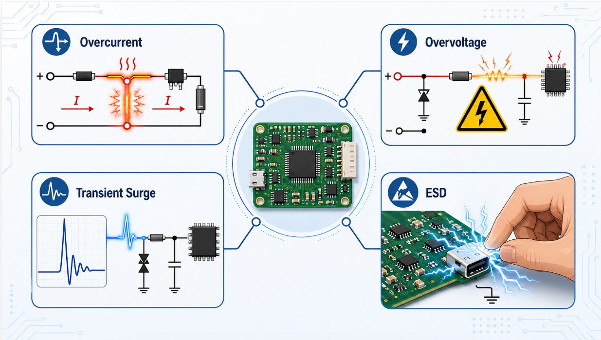
Different electrical threats damage circuits in different ways, so each protection device family solves a different problem.
These threats differ enough that the devices answering them work on opposite principles: some react to current, others to voltage; some open the circuit, others hold a voltage down. A protection strategy is therefore a set of choices, and naming the threat in front of you usually points to the right family.
Overcurrent Protection: Fuses, Resettable PPTC Polyfuses, and Circuit Breakers
Overcurrent devices watch for current that exceeds a safe level and remove the energy path before heat does harm. Eaton groups fuses and circuit breakers among the core families of circuit protection, and the TTI circuit protection guide frames overcurrent as the threat most often handled by a standard fuse, a resettable PPTC, or a breaker. The three differ mainly in what happens after they act.
When a one-shot fuse is the right call
A fuse is the simplest answer: a calibrated element that heats and opens permanently when current runs too high, interrupting the circuit until someone replaces it. Its clean, predictable break suits designs where faults are rare and a permanent disconnect is acceptable; the trade-off is downtime and a new part after each event. Rated current, time-current behavior, and interrupting capacity for a specific fuse live in the Littelfuse and Eaton/Bussmann datasheets.
When a resettable PPTC fits better
A PPTC, or polymer positive-temperature-coefficient device, is the resettable cousin of the fuse. Instead of opening permanently, it heats under fault current and switches to a high-resistance state that chokes the current to a trickle; once the fault clears and it cools, it recovers and conducts normally again. That self-recovery suits sealed assemblies and consumer ports where swapping a fuse is impractical. Hold current, trip current, and recovery characteristics belong to the Littelfuse PPTC datasheet.
Where circuit breakers belong
A circuit breaker interrupts like a fuse but can be reset by hand or mechanism, so it dominates at the panel and equipment-input level where currents are large and manual restoration is expected. It pairs a fuse's firm disconnect with reusability at higher power, and its trip curve and interrupting rating come from the manufacturer's documentation.
Overvoltage and Transient Protection: TVS Diodes, MOVs, and Gas Discharge Tubes
Overvoltage devices respond to voltage that climbs too high, and the most demanding case is the fast transient surge. Bourns, TDK/EPCOS, and the IEEE local-section presentation on selecting protection components describe the same three workhorses: TVS diodes, metal-oxide varistors, and gas discharge tubes, each sitting at a different point on the speed-versus-energy scale.
TVS diodes for fast, board-level clamping
A transient voltage suppression diode conducts almost instantly once voltage crosses its threshold, shunting the surge and holding the line near a defined clamping level while the circuit keeps running. That speed and tight clamp make the TVS the natural board-level, secondary protector near sensitive semiconductors. Its standoff voltage, clamping voltage, peak pulse power, and response time are datasheet parameters at Littelfuse, Nexperia, and Bourns.
Metal-oxide varistors (MOVs) and how they age
A metal-oxide varistor behaves like a high resistance at normal voltage and drops to a low resistance once voltage exceeds its threshold, clamping the overvoltage and absorbing energy. TDK/EPCOS material describes this switching behavior, which makes the MOV a common choice on AC inputs and power lines. Importantly, the IEEE presentation and TDK/EPCOS guidance note that an MOV can degrade with repeated surge events, shifting its characteristics over time. Varistor voltage, clamping voltage, and energy ratings come from the TDK/EPCOS and Bourns datasheets.
Gas discharge tubes for high surge energy
A gas discharge tube uses an ionizing gas gap that, once it sparks over, diverts very large surge currents to ground. It is slower to turn on than a TVS but handles far more energy, which is why it commonly serves as a primary stage against lightning-class events. Its spark-over voltages and surge current capacity are specified in the Bourns and Littelfuse datasheets. The table below summarizes relative ordering, not absolute values.
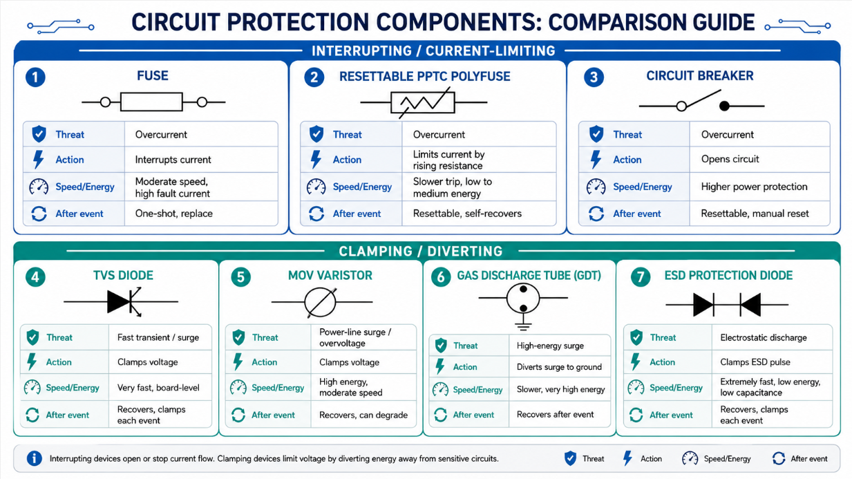
Protection components differ by threat type, reaction method, energy handling, speed, and recovery behavior.
| Device family | Primary threat | Typical role | Behavior after the event |
|---|---|---|---|
| Fuse | Overcurrent | Hard disconnect | One-shot; replace |
| PPTC polyfuse | Overcurrent | Current limit | Resettable; self-recovers |
| Circuit breaker | Overcurrent | Disconnect at higher power | Resettable; manual reset |
| TVS diode | Fast transient / ESD | Fast board-level clamp | Recovers; clamps each event |
| MOV / varistor | Surge on power lines | Energy clamp | Recovers; can degrade over time |
| Gas discharge tube | High-energy surge | Primary diversion to ground | Recovers; very high energy |
| ESD protection diode | Electrostatic discharge | Low-capacitance clamp on data lines | Recovers; clamps each event |
ESD Protection Devices for Data and I/O Lines
High-speed data and I/O lines need a protector that clamps electrostatic discharge without disturbing the signal beside it, and that is the job of a dedicated ESD protection diode. Nexperia's ESD portfolio centers on low-capacitance diodes built for connector pins on interfaces such as USB, HDMI, and antenna lines. Capacitance matters because any device on a fast line adds loading that corrupts high-speed signaling, so ESD diodes are engineered to clamp hard while staying nearly invisible to the data.
An ESD diode is not interchangeable with a varistor, even though both clamp overvoltage. Toshiba's comparison explains that they differ in behavior and directionality, so each fits a different role: the ESD diode for fast, low-capacitance protection on signal lines, and the varistor for absorbing surge energy on power lines. Line capacitance and discharge ratings for a given ESD diode are specified in the Nexperia and Toshiba datasheets.
Clamping vs Interrupting, One-Shot vs Resettable
Two distinctions drive most protection decisions. The first is clamping versus interrupting. A clamping device, such as a TVS, MOV, GDT, or ESD diode, limits or diverts voltage while the circuit keeps operating; it answers an overvoltage event without breaking the connection. An interrupting device, such as a fuse or breaker, opens the circuit entirely to stop current. The IEEE presentation, Eaton, and Littelfuse all reflect this split.
The second distinction is one-shot versus resettable. A one-shot part, like a fuse, must be replaced after it acts. A resettable part, like a PPTC or breaker, recovers or can be reset and continue protecting. The two distinctions are independent, and together they explain why a given part fits a given slot.
| Distinction | Option A | What it does | Option B | What it does |
|---|---|---|---|---|
| Response to the event | Clamping (TVS, MOV, GDT, ESD diode) | Limits or diverts voltage; circuit keeps running | Interrupting (fuse, breaker) | Opens the circuit to stop current |
| Recovery after acting | One-shot (fuse) | Replaced after it operates | Resettable (PPTC, breaker) | Recovers or is reset and reused |
How Layered (Coordinated) Protection Works in a Real Design
Serious input stages rarely rely on one part. They stage protection so a rugged primary device takes the brunt of a large surge and a faster, lower-clamp secondary device guards the sensitive electronics behind it. The IEEE selection presentation and application guidance from Bourns and Littelfuse describe this coordination directly: a high-energy primary stage, often a gas discharge tube or robust varistor, swallows most of the surge, while a fast TVS near the load clamps whatever passes through.
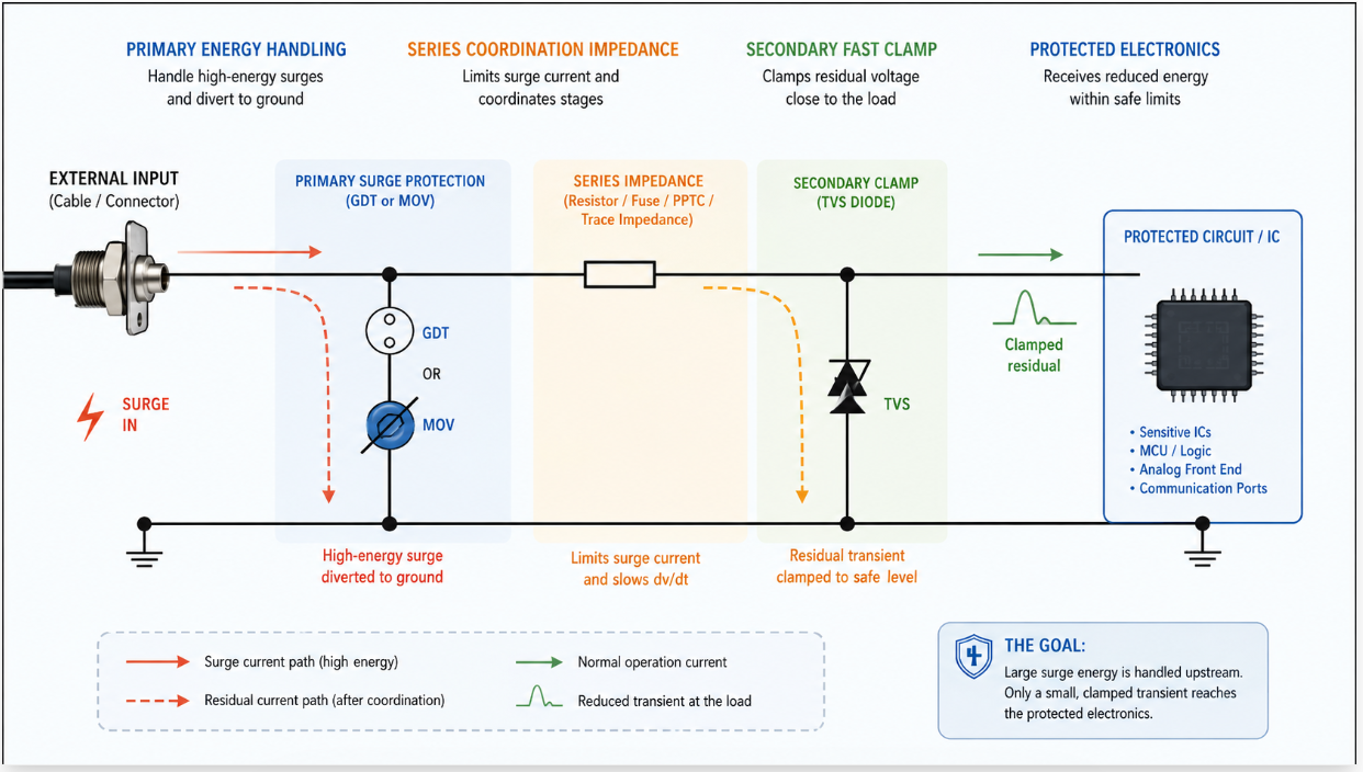
Layered protection lets a high-energy primary device absorb the bulk surge while a fast secondary clamp protects sensitive electronics.
The piece that makes the hand-off work is series impedance between the stages, frequently a small resistor or the natural impedance of a series overcurrent device. That impedance develops a voltage drop during the surge, encouraging the primary device to take the bulk of the current. It is also why a clamp on an input is often paired with a series fuse or PPTC: the TTI guide and Littelfuse guidance note that a sustained fault feeding a clamp can overstress it, so the series overcurrent element removes that energy path first.
How to Choose a Protection Device by Threat Type
For any line you are protecting, work through the same sequence before reaching for a part.
Name the threat: overcurrent, sustained overvoltage, a fast transient surge, electrostatic discharge, or a combination on one line.
Define the normal operating envelope so the device ignores the working voltage and current and does not nuisance-trip.
Judge what is downstream: a high-speed data input needs a fast, low-capacitance clamp, while a power rail needs energy handling and a firm disconnect on faults.
Pick the family that matches: overcurrent points to a fuse, PPTC, or breaker; surge and overvoltage point to a TVS, MOV, or GDT; ESD on signal lines points to a low-capacitance ESD diode.
Decide one-shot or resettable based on serviceability and how often you expect the event.
Confirm the exact ratings in the datasheet before committing the part.
For a mixed input facing both surges and faults, the practical answer is usually a layered combination: a clamp for the voltage event and a series overcurrent device for the sustained fault.
Where to Confirm Exact Ratings
Every parameter that decides whether a part is correct lives in the manufacturer datasheet, so treat those documents as the source of truth. Fuse, PPTC, and breaker currents come from Littelfuse and Eaton/Bussmann; TVS standoff and clamping voltage, peak pulse power, and response time from Littelfuse, Nexperia, and Bourns; varistor voltage, clamping voltage, and energy ratings from TDK/EPCOS and Bourns; gas discharge tube spark-over voltages and surge current from Bourns and Littelfuse; and ESD diode line capacitance and discharge ratings from Nexperia and Toshiba. The right number always depends on the exact part and its rated conditions.
Frequently Asked Questions
What is the difference between overcurrent and overvoltage protection?
Overcurrent protection responds to current that is too high for too long, typically by interrupting the circuit with a fuse, PPTC, or breaker before heat causes damage. Overvoltage protection responds to voltage that climbs too high, usually by clamping or diverting the excess with a TVS, MOV, or GDT while the circuit keeps running. They target different failure modes, so many designs include both.
What causes overvoltage in a circuit?
Overvoltage comes from several sources: switching transients when inductive loads turn on or off, energy coupled from nearby lightning strikes, faults in a power source or regulator, and electrostatic discharge from handling. Some are slow and sustained, others fast spikes lasting microseconds.
Is a TVS diode better than an MOV?
Neither is universally better; they suit different jobs. A TVS responds extremely fast and clamps to a tight level, which suits board-level protection of sensitive semiconductors. An MOV handles substantial surge energy and is common on AC and power lines, with the caveat that it can degrade after repeated surges. Many robust designs use them together, the MOV absorbing bulk energy and the TVS providing the final tight clamp.
What is the difference between a fuse and a resettable PPTC?
A fuse opens permanently when current is too high and must be replaced afterward, giving a clean, predictable disconnect. A PPTC instead raises its resistance to limit the current and then recovers once the fault clears and it cools, so it protects repeatedly without being swapped out. Choose a fuse where a permanent break is acceptable and a PPTC where self-recovery matters.
Where should ESD protection go on a board?
Place ESD protection diodes as close as practical to the connector or pin where the discharge enters, so the energy is clamped before it travels into the board. On high-speed lines, choose a low-capacitance diode so it does not degrade the signal.
Do I need more than one protection device?
Often, yes. A single device rarely covers both a fast surge and a sustained fault, and inputs frequently face more than one threat. Layered protection combining a primary energy-handling stage, a fast secondary clamp, and a series overcurrent device is common because each covers a gap the others leave open.
Why pair a clamping device with a series fuse?
A clamp limits voltage but keeps conducting during a sustained fault, which can overstress and eventually destroy it. A series fuse or PPTC removes the energy path when the fault persists, protecting the clamp from being driven beyond its capability. The pairing covers both the brief surge and the lasting fault.
Sources and References
Eaton electrical circuit protection confirms the common families of circuit protection, including circuit breakers, fuses, and surge protection. As a broad product overview, it is the right place to understand the categories but not the place to find exact part ratings.
Littelfuse circuit protection portfolio confirms the range of fuse, PPTC, TVS, varistor, and ESD families and is a primary destination for exact current and clamping ratings. Because it spans a large catalog, the specific numbers belong to each individual part datasheet rather than the overview.
Bourns circuit protection solutions confirms the MOV, GDT, TVS, and PTC families and supports coordination guidance. It points to device categories, so confirm the values for a chosen part in its dedicated datasheet.
TDK/EPCOS protection devices confirms metal-oxide varistor clamping behavior and surge product scope and is the destination for varistor ratings. It describes behavior at a product-family level, leaving exact energy and voltage figures to individual datasheets.
Nexperia ESD protection diodes confirms dedicated low-capacitance ESD diodes for data and I/O lines and is the destination for ESD diode ratings. It addresses the family broadly, so line capacitance and discharge figures come from each part's datasheet.
Toshiba ESD protection diode vs varistor FAQ confirms the qualitative differences between an ESD diode and a varistor, including directionality. It explains the distinction rather than providing selection numbers for a specific design.
TTI circuit protection guide confirms that overcurrent is commonly handled by a standard fuse or PPTC and supports the clamp-plus-series-fuse pairing. As an industry overview, it frames the approach but defers exact ratings to manufacturers.
IEEE local-section presentation on selecting circuit protection components confirms the comparative roles of GDTs, MOVs, fuses, and TVS diodes and the clamp-versus-interrupt and layered-protection framing. It is a conceptual presentation, so it guides selection logic rather than specifying parts for your board.
 UTMEL
UTMEL
We are the professional distributor of electronic components, providing a large variety of products to save you a lot of time, effort, and cost with our efficient self-customized service. careful order preparation fast delivery service
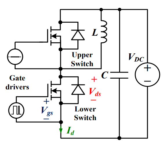 Discovering New and Advanced Methodology for Determining the Dynamic Characterization of Wide Bandgap DevicesSaumitra Jagdale15 March 20242900
For a long era, silicon has stood out as the primary material for fabricating electronic devices due to its affordability, moderate efficiency, and performance capabilities. Despite its widespread use, silicon faces several limitations that render it unsuitable for applications involving high power and elevated temperatures. As technological advancements continue and the industry demands enhanced efficiency from devices, these limitations become increasingly vivid. In the quest for electronic devices that are more potent, efficient, and compact, wide bandgap materials are emerging as a dominant player. Their superiority over silicon in crucial aspects such as efficiency, higher junction temperatures, power density, thinner drift regions, and faster switching speeds positions them as the preferred materials for the future of power electronics.
Read More Applications of FPGAs in Artificial Intelligence: A Comprehensive GuideUTMEL29 August 20255654
This comprehensive guide explores FPGAs as powerful AI accelerators that offer distinct advantages over traditional GPUs and CPUs. FPGAs provide reconfigurable hardware that can be customized for specific AI workloads, delivering superior energy efficiency, ultra-low latency, and deterministic performance—particularly valuable for edge AI applications. While GPUs excel at parallel processing for training, FPGAs shine in inference tasks through their adaptability and power optimization. The document covers practical implementation challenges, including development complexity and resource constraints, while highlighting solutions like High-Level Synthesis tools and vendor-specific AI development suites from Intel and AMD/Xilinx. Real-world applications span telecommunications, healthcare, autonomous vehicles, and financial services, demonstrating FPGAs' versatility in mission-critical systems requiring real-time processing and minimal power consumption.
Read More The 2026 Engineer’s Guide: Choosing the Right MCU for Your Next IoT & New Energy ProjectUTMEL30 April 20261967
A comprehensive comparison of 2026's leading MCUs from ST, NXP, and Microchip across power efficiency, processing performance, connectivity, and ecosystems to help engineers select the optimal chip for next-gen IoT and new energy projects.
Read More AI Server Components: Engineering Next-Gen Data Center Hardware for 100kW RacksUTMEL15 May 20261046
The transition from traditional enterprise IT to AI-driven workloads has rendered legacy data center hardware obsolete, forcing infrastructure planners to re-engineer server components for extreme thermal environments.
Read More The Practical Engineer’s Guide to the NE555N Timer: Pinout, Setup, and TroubleshootingUTMEL29 May 2026861
This comprehensive guide explores the NE555N timer, detailing its 8-pin layout, internal architecture, and key datasheet specifications. It compares the bipolar IC to CMOS variants and details setup configurations for astable, monostable, and bistable modes. Additionally, the guide offers practical troubleshooting advice to prevent common breadboard failures, such as floating reset pins and electrical noise issues.
Read More
Subscribe to Utmel !
![MOC3073SR2M]() MOC3073SR2M
MOC3073SR2MON Semiconductor
![FM31278-GTR]() FM31278-GTR
FM31278-GTRCypress Semiconductor Corp
![HCS410/P]() HCS410/P
HCS410/PMicrochip Technology
![L9654TR]() L9654TR
L9654TRSTMicroelectronics
![AT88SC6416C-MJTG]() AT88SC6416C-MJTG
AT88SC6416C-MJTGMicrochip Technology
![MOC3062SVM]() MOC3062SVM
MOC3062SVMON Semiconductor
![HCS512T-I/SO]() HCS512T-I/SO
HCS512T-I/SOMicrochip Technology
![LZ9FC23]() LZ9FC23
LZ9FC23Sharp Microelectronics
![HCS370/ST]() HCS370/ST
HCS370/STMicrochip Technology
![MCS3142-I/ST]() MCS3142-I/ST
MCS3142-I/STMicrochip Technology


